|
|
|
|
[Contents] | [Index] |
Cooperation with: S. Eichler (Freiberger Compound Materials GmbH (FCM))
Supported by: Freiberger Compound Materials GmbH
Description:
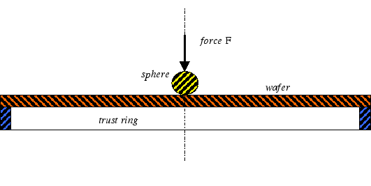
In 2000 we have started a remittance study on the stress distribution in a thin wafer plate which is loaded by the steel sphere according to Fig. 1.
The wafer plate's material is single crystal GaAs the [100] direction of which is parallel to the load axes. Preliminary studies have shown that the external load induces a deformation field that has small strain components, however, the rotational contribution to the deformation field is quite large, so that the appropriate field equations are the nonlinear von Kármán equations in Lagrangian coordinates. The complete elliptic von Kármán system is to be found in the WIAS Annual Report 2000, and we refer the reader to pp. 120-122. The von Kármán system results, by a limiting process, from the 3-d nonlinear elasticity system for the second Piola-Kirchhoff stress tensor
 |
(1) |
 |
(2) |
During the time of the current annual report we finished all necessary calculations, and we proceeded according to the following items:
1. The von Kármán system revisited
We have rederived the von Kármán system from a different point of
view as it was considered in the year 2000. While we started at first from
special kinematic assumptions in order to reduce the cubic anisotropic 3-d
system of elasticity to the von Kármán system, the new
derivation relies on some simple assumptions regarding the dependence of the
displacement and stress components ui and ![]() ,respectively, on the thickness h of the plate. In particular, we now
conclude, relying on an asymptotic expansion for the displacement, that the
main contributions to the displacements are of the form
,respectively, on the thickness h of the plate. In particular, we now
conclude, relying on an asymptotic expansion for the displacement, that the
main contributions to the displacements are of the form
| u1 | = | ||
| u2 | = | (3) | |
| u3 | = |
| (4) |
2. The contact problem sphere/plate
The distribution of the load over the contact surface is given by
 |
(5) |
3. The boundary conditions
It is crucial for the correct modeling of the actual technical
problem that in particular the boundary conditions at the thrust ring
are prescribed appropriately. A comparison of the maximal displacement
according to the mathematical simulation with the experimental data
has revealed that the material points of the plate that coincide
initially with the inner circle of the thrust ring do not remain
there, rather the plate may glide without friction. This fact leads to
the phenomenon that the stress resultant tensor ![]() is
continuous across the inner thrust line. Because the plate can
additionally rotate freely here, the bending moment tensor
is
continuous across the inner thrust line. Because the plate can
additionally rotate freely here, the bending moment tensor ![]() is also continuous across the thrust line. From preliminary
test calculations we know that there are only compressive forces along
the thrust line, so that the 3-component of the displacement W
vanishes here.
is also continuous across the thrust line. From preliminary
test calculations we know that there are only compressive forces along
the thrust line, so that the 3-component of the displacement W
vanishes here.
The outer boundary of the plate is free of stress:
 |
(6) |
4. The numerical simulation
The von Kármán system is numerically solved by a finite
element method. The finite-element net consists of triangles that have
36 degrees of freedom. The 3- displacement W is given in each of the
outer nodes of an element by a 6- parameter Hermitian ansatz
which is C1 continuous. Thus the value of the ansatz function and
its two first derivatives can be described. The two other
displacements U and V are given in each of the outer nodes of an
element by a 3- parameter Hermitian ansatz which is C0
continuous. Thus the value of the ansatz functions and their first
derivatives can be described. Consequently, we obtain for each
triangle an algebraic nonlinear coupled system for 36 unknowns with a
symmetric Jacobian.
5. The Kirchhoff system
The accuracy of the used elements is tested by the Kirchhoff
system, which results as the limiting case of the von Kármán
system for very small bending. The elements used approximate the analytic
solution of the Kirchhoff system already up to five mantissae even
for a very rough net.
6. The crucial test of accuracy
The FCM has compared the maximal displacement versus the external load
according to the WIAS calculation of the von Kármán system
with their own careful measurements. Figure 2 shows the perfect
matching of the simulation with the experimental data. It is important to
note that the WIAS result is in fact a prediction, and does not contain any
fitting procedure. However, if the load is increased beyond ![]() , a
difference between simulation and the experiment begins to grow. The range
of applicability of the von Kármán system is reached, and
further nonlinear contributions of the complete 3-d elasticity system must be
incorporated.
, a
difference between simulation and the experiment begins to grow. The range
of applicability of the von Kármán system is reached, and
further nonlinear contributions of the complete 3-d elasticity system must be
incorporated.
References:
|
|
|
[Contents] | [Index] |