|
|
|
|
[Contents] | [Index] |
Collaborator: E. Bänsch , J. Fuhrmann , M. Uhle
Cooperation with: H. Baltruschat, Th. Löffler (Rheinische Friedrich-Wilhelms-Universität Bonn, Institut für Physikalische und Theoretische Chemie)
Description:
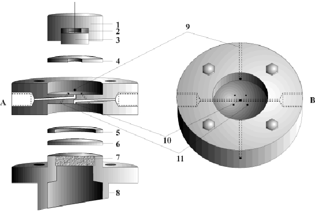
We consider a new coupled thin layer cell (TLC) described in [1] suitable for analysing electro-chemical processes at metal electrolyte phase boundaries with differential electro-chemical mass spectrometry. A coupled thin layer cell (see Fig. 1) is characterized by separation of the area of electrodes (3) and an additional area which enables the electrolyte to flow through a membrane (6) to a mass spectrometer. They are connected by capillary vessels (11).
|
|
We are planning to analyze the following experiment, which is important for basic research of fuel cells: a water-soluble substance (methane) streams from input (A) to an electrode (3), which has a large surface area to cell volume ratio, i.e. the layer (4) is very thin. At the surface of the electrode a chemical reaction occurs. The chemical products of the reaction stream through the capillaries (11) to the membrane (6) and through the steel frit (7) to the mass spectrometer, while other chemical products flow to output (B).
We are interested in the reaction rate on the electrode. The amount of source and target substance is measured by the mass spectrometer. By detecting the amount of molecules of the target substance, one can determine the rate of reaction at the electrode.
The geometry of thin layer cells, the drift of electrolyte, process and material parameters play crucial roles in the chemical reaction process, and in determining the kind of reaction products.
As a first means of modeling the chemical process,
the TLC is assumed to be cylindrical. The
model of the cross-section of the TCL is shown in Fig. 2
indicating
the simulation area ![]() as a bounded domain.
as a bounded domain.
In this particular model, we consider the capillary vessels as radial passages to the membrane area. We further assume that there are no external forces acting on the TLC. Also, the drift components of the electrolyte in the azimuthal direction are neglected.
Essentially, two basic physical processes need to be formulated: the drift of the electrolyte, and the diffusion and the concentration of the reaction products.
The hydrodynamics of the process is modeled by the incompressible Navier-Stokes
equations:
![]()
The flow in the TLC through ![]() (see Fig. 2) is
modeled by a quadratic profile
(see Fig. 2) is
modeled by a quadratic profile
![\begin{displaymath}
u_z\vert _{\Gamma_1} = U [ 1 - (\frac{r}{r_o})^2],\quad u_\phi\vert _{\Gamma_1} = 0, \quad u_r\vert _{\Gamma_1} = 0,\end{displaymath}](../2001/img218.gif)
Initial numerical results have been obtained for the velocity field of the electrolyte (see Fig. 3).
The rate of concentration is calculated by the following equation with
given velocity ![]() :
:
| |
(2) |
Boundary conditions which fulfil equation (2) need to be
addressed:
first, the electrolyte is taken to be homogeneous at input
(![]() ), i.e.
), i.e. ![]() ;
secondly, we assume the source substance is fully
converted at the electrode (
;
secondly, we assume the source substance is fully
converted at the electrode (![]() ), i.e.
), i.e. ![]() ; thirdly,
only the reaction products can diffuse through the membrane
(
; thirdly,
only the reaction products can diffuse through the membrane
(![]() ); finally,
homogeneous Neumann conditions are defined at all other boundaries
(
); finally,
homogeneous Neumann conditions are defined at all other boundaries
(![]() ).
).
The computations are carried out in cylindrical coordinates using algorithm [3]. As yet, attemps at numerical simulation have led to problems, mainly caused by different local spatial discretization schemes; whereas the finite-volume scheme [3] for equation (2) assumes a divergence-free velocity field, the finite-element method developed in [2] for equation (1) can only guarantee this property to hold approximately.
The solution of this problem, calculations of reaction rates near the electrode surface, and a detailed modeling of the electro-chemical process will be addressed in current and future work.
References:
|
|
|
[Contents] | [Index] |
![% latex2html id marker 4973
\parbox {0.50\textwidth}{\html{\stepcounter{projektb...
...ktbild \arabic{projektbild}]{Cylinder-symmetric
discretization
}
\end{figure}}](../2001/img219.gif)
![% latex2html id marker 4975
\parbox {0.47\textwidth}{\html{\stepcounter{projektb...
...ektbild \arabic{projektbild}]{Velocity field of the electrolyte
}
\end{figure}}](../2001/img220.gif)